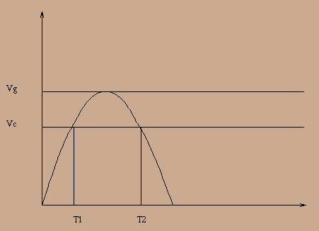
It's now time to compromise : we will assume in the following section
that we will be working with a capacitive loading schema in which
capacitor has a sufficient value so that voltage at its terminals is
nearly constant. If we assume too that there is no voltage drop across
the rectifier (every situation is reducible to this one simply by
adding voltage drop to output voltage), current will flow thru it only
when input voltage will excedd ![]() . This occurs in the time
intervall
. This occurs in the time
intervall ![]() as depicted in the figure below :
as depicted in the figure below :

The intervall ![]() can also be represented by an angle
can also be represented by an angle ![]() :
:
![]()
![]() is called the opening angle of the rectifier. Instantaneous
current in the load is then computed easely as :
is called the opening angle of the rectifier. Instantaneous
current in the load is then computed easely as :
![]()
which yields, by an elementay integration to the following formula for
mean current :
![]()
(we recall that n is the number of phases). ![]() is mean current
flowing thru the load and is generally given in specifications of the
power supply : it is then possible to find
is mean current
flowing thru the load and is generally given in specifications of the
power supply : it is then possible to find ![]() knowing that
current, and, since
knowing that
current, and, since ![]() is specified too, to compute unloaded
voltage
is specified too, to compute unloaded
voltage ![]() . By putting
. By putting ![]() , one has the short circuit current :
, one has the short circuit current :
![]()
yielding an equivalent expression for mean current :
![]()
Since Ohm's law gives ![]() , it comes :
, it comes :
![]()
Finally, using ![]() definition, namely
definition, namely ![]() , one has the following formula :
, one has the following formula :
![]()
This expression can be used to compute ![]() knowing power supply
and load internal resistances.
knowing power supply
and load internal resistances.
One needs now to know if filtering is efficient enough. For that,
current's fundamental wave amplitude ![]() will be enough : since a
rectifier is almost never used without an auxilliary low-pass filter,
one can admit that harmonics have a negligeable contribution to total
hum. A fourier transform gives :
will be enough : since a
rectifier is almost never used without an auxilliary low-pass filter,
one can admit that harmonics have a negligeable contribution to total
hum. A fourier transform gives :
![]()
Which is for most usual values of n :

From the amplitude ![]() , residual waving at capacitor terminals is
obtained by multiplying with its impedance :
, residual waving at capacitor terminals is
obtained by multiplying with its impedance :
![]()
where f is mains frequency. This formula can be rewritten in the
case of a 50Hz mains (correct that if you have a 60Hz mains!) :

In all previous computations, we have assumed (without saying it) that
capacitor impedance is low when compared to that of the load, making
possible to admit that all hum current is flowing thru the
capacitor. In practical applications, if a RC filtering is used (see
next sections), this hypothesis can be false and computed hum can be
slightly lower than observed one (several percents). It is almost
never a problem, but for some critical applications accuracy is
needed : on can then compute total load impedance Z knowing
auxilliary filter impedance ![]() by :
by :
![]() thus the hum voltage (
thus the hum voltage (![]() expression
is always valid) :
expression
is always valid) : ![]() .
.
Main characteristics of the power supply are now
knowned. Nevertheless, mains transformer must still be designed, and
for that purpose, RMS intensity of secundary current is
needed. this value is easely computed by integration of the
instantaneaous current :

or alternatively :
![]()
thus, using ![]() and
and ![]() relationship :
relationship :
