A rectifier is basically a thresholding non linear component : below a given voltage, no (or a very small) current will flow, then, this value beeing exceeded, conduction occurs. Altough almost all rectifiers have a threshold of 0 volts (what do not mean, at least for high vacuum valves, that their voltage drop is small at full load), it exists a special category of rectifiers, the gaz filled diodes, for which behaviour is far more complex. For those components, below the trigger voltage, no conduction occurs, then, after that, chain ionisation begins (tube will glow!). As soon as the discharge is started, voltage drop at the tube terminals is almost constant (internal impedance is very low). The tube will switch off only when voltage will fall below the extinction threshold, which is different from the ignition threshold! Gaz filled diodes must never be used with a capacitive load, except when explicity mentionned in the data sheet (in which case maximum value for the capacitor should never be exceeded) : internal impedance is so low that charge current at start up will destroy the tube (the same phenomenon can occur will silicon diodes).
Notation We will use the following symbol for all rectifiers (except gaz filled ones), regardless of the technology :

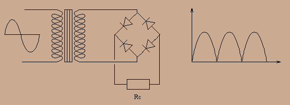
For a mains supply, three basic schemas can be used (wave at load terminals is indicated to the right) :
Monophased rectifying :

Biphased rectifying :

Graetz brige rectifying :

If we denote internal impedance of rectifier plus that of windings
(see article on transformers) by ![]() and if the load can be modelled
as a pure resistance
and if the load can be modelled
as a pure resistance ![]() , instantaneous value of voltage at load
terminals is :
, instantaneous value of voltage at load
terminals is :
![]()
where ![]() is the unloaded transformer voltage. An elementary
computation shows that mean value of
is the unloaded transformer voltage. An elementary
computation shows that mean value of ![]() is :
is :

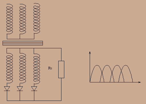
Previous schemas can be generalised to multiphased current : here is
an example of triphased rectifying, used in high power applications :

In the following, the number of phases will be denoted by n, and this will be a parameter of all formula. An amateur will probably not be using hexaphased current, however, it will appear in the following that filtering is easier when number of phases increases. Purist audiophile can try to reconstruct multiphase waves with an onduler.